AmateuRadioMalaysia

Sunday, December 25, 2005

Do you know Series - 11


It is a common perception that it requires sophisticated equipment and large circularly polarised antenna arrays to work amateur satellites. There are several low Earth orbiting satellites which can be worked with relatively simple transceivers and antennas.

More recently, some satellites have been carrying crossband FM repeaters instead of linear transponders. These repeaters are similar to their familiar terrestrial cousins in that they receive an FM signal on a specific channel, demodulate the signal and retransmit the signal on a new frequency. These satellites can only carry one QSO at a time.

To successfully work an amateur satellite, you need to have transceivers suitable for the satellites you wish to work. For the FM repeaters, either a dual band FM transceiver with crossband transmit/receive capabilities or separate 2m and 70cm FM transceivers are suitable. All of the FM satellites (operational or proposed) use 2m and 70cm, with one of these bands being used for the uplink, the other for the downlink.

There are a wider variety of frequencies in use by linear transponder satellites. The suggested bands to try for a first attempt are 2 metres uplink and 10 metres downlink. Example:

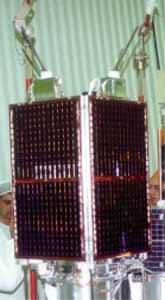
AMSAT-OSCAR 51 (Echo or AO-51)
Analog Uplink:
145.920 MHz FM (PL - 67Hz)145.880 MHz FM QRP (no PL)1268.700 MHz FM (PL - 67Hz)
Analog Downlink:
435.300 MHz FM2401.200 MHz FM
PSK-31 Uplink
28.140 MHz USB
Digital Uplink:
145.860 MHz 9600 bps, AX.251268.700 MHz 9600 bps AX.25
Digital Downlink:
435.150 MHz 9600 bps, AX.252401.200 MHz 38,400 bps, AX.25
Broadcast Callsign:
PECHO-11
BBS Callsign:
PECHO-12
Launched
June 29, 2004
Status: Operational

For antennas, an existing HF dipole and VHF/UHF omnidirectional antennas will work in a pinch. The typical VHF/UHF collinears typically have a low angle of radiation, and better results may be obtained with a simple ¼ wave groundplane, or for the more serious, a turnstile antenna. If you have crossed Yagis and AZ/EL rotators, all the better (but then this article isn’t aimed at you in this case! :-) ). Finally, though not essential, it is very strongly recommended to have a computer, satellite tracking software and an Internet connection available. The Internet connection is for downloading the latest Keplerian elements for the tracking software (and the software itself if you don’t have any), as well as checking satellite home pages for transponder schedules and other information. Besides, the Internet is fun when the birds aren’t overhead!

Working your first satellite! This isn’t anywhere near as daunting as it sounds. The first thing is to have a look around your shack and see what equipment you have. If, like many amateurs, you have FM only radios on VHF/UHF, then you are limited to the FM satellites. The rest of this article will concentrate on FM operation as nearly everyone has FM gear for 2m and 70cm, and the operating techniques are easier to master.

First, time for an inventory, as the gear you have available will partially determine the satellite to use. Regardless of the rig you use, it has to be capable of tuning in 5 kHz or smaller steps, to enable you to follow the Doppler shift as the satellite passes overhead.

Home operators will most likely use their existing omnidirectional or beam antennas. Modern omnis tend to have a very low angle of radiation and therefore may not give good results when used to work satellites. However, as most modern rigs put out 35-50 watts on 70cm, the extra power should largely compensate for the antenna’s radiation pattern. If you can use a ¼ wave or turnstile though, then you’ll enjoy better satellite performance. If you have a beam, you will need to track the satellite as it passes, especially at low angles, where the beam’s gain will be useful. And finally, don’t forget an earpiece or headphones. You will be operating full duplex (i.e. being able to transmit and receive simultaneously) and without headphones, feedback can be a problem. With them, you’ll be able to hear what you sound like while you transmit, which will be helpful for correcting for Doppler shift.

Only one person can use the transponder at a time and the satellite is usually only accessible for about 10 minutes. Others will appreciate your efficiency and courtesy. Most FM satellite contacts are usually an exchange of callsigns, signal reports and occasionally a comment about the weather.

The typical station is:
Uplink - Icom IC-T81A handheld running 3.5 watts into a 70cm 1/2 wave ground independent handheld whip.
Downlink - Alinco DJ-500T handheld or Standard C58 all mode portable with a "ScanDucky" scanning antenna (roughly equivalent to a 1/4 wave on 2m).

However, a word of warning: For some people, the thrill of satellite operation can be addictive! You may find yourself trying unusual situations, or decide to invest in multimode gear and work some of the linear 'birds' that are up there. You have been warned! (and I have the audio clips and 2m all mode box to prove this theory!) :-)

Courtesy & edited from AMSAT Web page :
http://www.amsat.org/amsat-new/information/faqs/langdon.php


Tuesday, December 20, 2005

Customised GPS Garmin Maps for Malaysia and Singapore

Dear All,

Get Ready GPS data Malaysia and Singapore
In order to make things easy for everyone. I have included
A ready made map of Singapore and Malaysia ready to upload to your Garmin Mapping GPS.
The source file for the maps based on malaysiagis.com data

http://www.malaysiagis.com/related_technologies/gps/resources4.cfm


Welcome to the portal of GPS Maps of Malaysia & Singapore1. This site provides FREE GPS maps of Malaysia and Singapore for use with Garmin GPS receivers.2. With the correct setup and software, these maps can also be made to work with GPS enabled PDA's running on PPC environment.3. Please use these maps with caution and at your own risk!

http://malsingmaps.com/

Tuesday, December 13, 2005

Malaysia Spectrum Plan

As some one was asking..

Here is the Band Plan link at MCMC

http://www.mcmc.gov.my/what_we_do/spectrum/pdf/planv2_3.pdf

Some of the pertinent bands that affect Amateurs:


Saturday, December 10, 2005

Do you know Series - 10

Do you know your Malaysian Satellites?

TIUNGSAT-1 (MO-46)

Uplinks
145.850,145.925 MHz 9600 baud FSK
Downlink
437.325 MHz 38.4K Baud FSK

Broadcast Callsign
MYSAT3-11
BBS
MYSAT3-12
NUP
MYSAT3-10

Launched
26 September 2000Status: Operational
TiungSat-1 is Malaysia's first micro-satellite and in addition to commercial land and weather imaging payloads offers FM and FSK amateur radio communication.


Info from http://www.amsat.org web page


Objectives

The TiungSAT-1 microsatellite mission carries the following payloads:
Multi-Spectral Earth Imaging System (MSEIS)
The MSEIS provides high quality approximately 80-metre ground sampling resolution multi-spectral images in 3 bands (Near Infra-Red, Green and Red) using 1024x1024 pixel 2-dimensional CCD array detector digitised to 8 bits radiometric resolution (256 levels). The image swath width is 80 km and each imager can collect 4 images contiguously along the flight path.
Meteorological Earth Imaging System (MEIS)
The MEIS provides high quality meteorological wide-field images (Near Infra-Red) with 1.2 km ground sampling using 1024x1024 pixel 2-dimensional CCD array detectors digitised to 8 bits radimetric resolution (256 levels). The images swath width is 1200 km and the imager can collect images contiguously along the flight path.
Digital Store-&-Forward Communications (S&F)
S&F communications provides global, frequency-agile, communications for any form of digitised data: e-mail, voice-mail, scientific data exchange, fax, images, or even Internet mail for remote regions. The low cost and direct access offered by theTiungSAT-1 microsatellite in orbit also makes it ideal for use by scientists, engineers and students based in institutes, universities and even schools throughout the world.
Digital Signal Processing Experiment (DSPE)
The DSPE consists of TM320C31 low power Digital Signal Processor suitable for special or general purpose signal processing tasks on LEO satellites.

Payload Information

Spacecraft
...........................
Spacecraft Mass 50 kg (platform: 35 kg; payload: 15 kg)
Spacecraft Envelope 690 x 360 x 360 mm
Communication Systems Supporting data rates from 9.6 kbps to 76.8 kbps at VHF/UHF
On-board Computers Primary 186EX OBC (16 Mbytes of SRAM EDAC). Secondary 386EX OBC with 387 co-processor (128 Mbytes of SRAM). They both use an in-orbit reloadable on-board real-time, multi-tasking operating system with high level, user friendly (C-language) application software.
On-board Data Handling Via Controller Area Network (CAN) between platform and payloads
Attitude Determination Using 3-axis vector magnetometer (+/- 60,000 nT, 30 nT resolution) and 2-dimensional sun angle sensors provides attitude restitution to within 0.5 degree.
Attitude Control Earth pointing to within 3 degrees using 6-metre boom gravity-gradient stabilisation and advanced on-board Kalman filter to control the magnetorquer.
Orbit Determination Using a 12-channel GPS receiver provides on-board positioning within 100m and autonomous Keplerian orbit determination.
Power Generated from high-efficiency 35W GaAs solar arrays provides 50W peak and 20W continuous orbit-average spacecraft power, which is stored using 7Ah NiCd batteries.
Science Payload
Cosmic-Ray Energy Deposition Experiment (CEDEX) The purpose of CEDEX is to characterise the TiungSAT-1 (Sun-Synchronous) orbit radiation environment in terms of the observed particle Linear Energy Transfer (LET) spectrum at the spacecraft. The data returned by the instrument are directly comparable to that obtained by similar instruments such as U.K.'s Cosmic-ray Effects and Dosimetry (CREDO) and Cosmic-Ray Effect and Activation Monitor (CREAM) experiments which have flown on-board Corcorde, the U.S. Space-Shuttle and UoSAT-3, and the Cosmic-Ray Experiment (CRE) flown on KITSAT-1 and PoSAT-1. These data are also be of great use in evaluating the radiation performance of the electronics used in the TiungSAT-1 satellite.
The primary sensor consists of a 30mm x 30mm PIN diode detector (900 mm2 active area), 300 microns in depth, housed in a separate screened aluminium unit mounted on the CEDEX module box. This is connected to a charge amplifier and a pulse-shaping circuit which, in turn, are connected to an event-driven, hardware-logic controlled pulse-height multi-channel analyser. The experiment is controlled autonomously by a CAN-microcontroller with its own data-storage RAM and built-in data-compression software. This sends data to an internal CAN-controller which formats and sends them on to the primary OBC via the spacecraft's CAN bus.
Ionespheric Space Science An advanced 12-channel GPS receiver on-board the TiungSAT-1 microsatellite will be used primarily for determining the orbit and position of the microsatellite to within 100 metres and also to provide precise and accurate timing for spacecraft timing for spacecraft functions and payloads.
By positioning two GPS antennas on-board TiungSAT-1, the position of the microsatellite can be determined from GPS satellites in good view and compared with signals received from other GPS satellites as they dip down through the Earth's ionosphere. The timing delays and phase changes due to the diffraction that result can yield information on the electron density profile of the ionosphere and its fluctuations.

Communications

The RF communications subsystem enables the ground stations to communicate both telemetry, telecommand and payload data to and from the space craft in orbit. It consists of UHF (435 to 438 MHz) downlink transmitters with modulator and VHF (144 to 146 MHz) uplink receivers with demodulator. The exact operating frequency of the uplink and/or the downlink can be selected under ground or on-board control, within a limited range. Communications for telemetry, telecommand and payload data are provided using error-protected digital packet communications at VHF and UHF at rates from 9.6 and 38.4 kbps, and experimentally at 76.8 kbps.
The downlink system consists of two transmitters, primary and one cold standby (secondary). One transmitter has a variable power output of up to 10 W, the second transmitter has a fixed power level of 1.5W measured at the transmitter output when the battery is at maximum charge and operated at the expected operating temperature.
The uplink system is triple redundant. Two primary uplink receivers are provided. Each has a separate LNA and two-frequency switch. A third receiver is the command receiver and does not have a LNA, this makes it both more reliable and less susceptible to interference. Once past the antenna, the uplink system includes no single point failure nodes. All three uplink receivers operate at 9.6 kbps rate.
The uplink VHF antenna consists of 4 monopoles. The antenna is linearly polarised and has a gain of approximately 0 dBi. The downlink UHF antenna system consists of 4 monopoles. Either the primary or the redundant transmitter chain can be connected to the downlink antenna through a latching relay controlled by on-board or ground-initiated telecommand.
Power Subsystem
The power subsystem conditions and distributes solar-generated electrical energy for the entire spacecraft. It provides regulated voltage supplies at +5V and ±10V along with an unregulated supply which fluctuates between 12V and 14V (depending upon the battery state of charge).
Four 330 x 530 mm solar array panels are mounted directly to the satellite body. These panels comprise Gallium-Arsenate (GaAs) solar cells for high conversion efficiency. The overall panel efficiency typically delivered from these panels is 19.5%, and the beginning of life (BOL) orbit-average power available is 20W.
The spacecraft battery is built from 10 NiCd cells. The battery has a capacity, at standard operating temperature, of 7Ah and a nominal operating voltage of 12 - 14V. The battery permits operation of payload and platform subsystems throughout eclipse periods and also provides limited-duration peak powers in excess of the capability of the solar panels.
Groundstation
A comprehensive satellite mission operations and control groundstation is being installed at Department of Physics, Universiti Kebangsaan Malaysia (Latitude: 2.917 degree North and, Longitude: 101.78 degree East). A standard Mission & Control Groundstation (MOCGS) to provide a cost-effective primamry station for mircosatellite mission has been designed. All components of the ground station, from uplink and downlink antennas to data archiving computers, have been chosen to provide an optimal compromise between cost, reliability and performance.

http://www.ee.surrey.ac.uk/SSC/CSER/UOSAT/missions/tiungsat/index.htm