AmateuRadioMalaysia

Friday, August 11, 2006

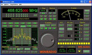
Software controlled Radio


This is a canggih Radio that costs several thousand Ringgit to buy.

WR-G313i

Overview
The WiNRADiO WR-G313i is a software-defined high-performance HF receiver (9 kHz to 30 MHz, optionally extendable to 180 MHz) on a PCI card.
This receiver is intended for government, military, security, surveillance, broadcast monitoring, industrial and demanding consumer applications.

The receiver is extremely sensitive, making it possible to comfortably read CW signals under 0.05 µV input levels, yet featuring a respectable 95 dB dynamic range making the receiver resistant to strong signal overload. The high sensitivity is also matched by that of the S-meter: The fully calibrated S-meter shows the received signal levels in dBm, µV or S-units, down to the ‑140 dBm noise floor.
The hardware and software package consists of the receiver card, Windows-based software, a start-up antenna and a user's manual.

Hardware

The PCI card plugs into an available slot of an IBM-compatible PC. Several receivers (as many as there are free PCI slots available) can be controlled by a single PC - an ideal solution for high-performance multi-channel automatic monitoring systems.
There is a single SMA antenna connector and an output line audio jack which can be used to connect the receiver output directly to a sound card line-input or an amplified speaker.
The receiver has its own on-board DSP, and does not rely on the PC sound card for its performance. As the DSP performs the final stage IF filtering and all demodulation, this receiver is entirely software-defined, which means that additional demodulation or decoding modes can be easily added by a mere software change. (For example, an optional DRM decoder/demodulator is also available.)
No cables or power supplies needed - no clutter on your desk. Every modern desktop computer can be converted into a powerful HF monitoring station with minimum fuss.

Software
The WR-G313i software contains numerous advanced features, many tuning and scanning options, virtually unlimited memories and a rich on-line help facility:

Another useful feature, previously unavailable with receivers of this price class, is a test and measurement facility, performing measurements on the received signal including frequency accuracy, amplitude modulation depth, frequency deviation, THD (total harmonic distortion) and SINAD. An audio spectrum analyzer is also included, making it possible to observe the demodulated spectrum in real-time with a resolution of 5 Hz.

What's included?
The standard WR-G313i package includes:
WR-G313i receiver card Application software Comprehensive user's manual Start-up antenna Audio lead BNC-to-SMA adapter

System requirements:
PC with 500 MHz Pentium CPU or faster One free PCI slot Windows 98/ME/2000/XP

Sunday, August 06, 2006

Using TVRO Dish for a Ham Antenna

Dishes for Amateurs

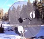
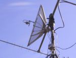
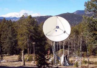
The price was right for this dish - FREE. Wives call them BUDs (Big Ugly Dishes). It was originally used for 4 GHz TV Receive Only (TVRO). Replacing the C band feed at the focal point turned it into a great ham antenna. On a 10' dish, the tri band feed has measured 35 db of gain on 2401 MHz, 29 db of gain on 1269 MH, and 18 db on 435 MHz. 35 db of gain makes a 1 watt signal sound like 2 KW! This feed system works AO-40 with as little as 1/10 of a watt on 1269 MHz achieving maximum allowed signal level into AO-40. Take the C band feed off that old TVRO dish and attach a ham band feed system and convert the mount to elevation and azimuth automatic control for a great ham satellite antenna system.

A TVRO dish can be can be converted with minimal effort to function very well in a number of uses. Other uses are EME (Earth-Moon-Earth) experiments, Radio Astronomy, and SETI (Search for Extraterrestrial Intelligence).
TVRO dishes should work great on DSP EME.

Amateur Dish Types
Dishes come in many sizes and shapes. Each has advantages and disadvantages, so it is important to understand several items. Don't start off on a giant sized dish; start small and build up to the giant sized dish. Doubling the size of your dish will gain you 3 db, but may take 20 db of effort!
General - Diameter, Focal Length, Construction, Gain, Beamwidth, & Windloading
Small - 18" Hubcaps, 3' Barbecue Grills, PrimeStar Offset fed
Medium - 4' Aluminum solid, 5' Aluminum mesh, 6' Aluminum solid, 7 1/2' Aluminum mesh
Large - 10' Steel Mesh, 10' - 14' Fiberglass, 15' - 16' , Giants

Dish Feed Systems
You have to put out a signal to the dish or receive a signal reflected by the dish. But all dish feed systems are not equal, and a dish feed system that works great on one dish may be a real loser on another dish. At 2401 MHz, a Campbell's soup can lid makes a nice antenna and a peach can makes a scalar ring reflector.
Dipoles & Reflectors
Single band Helix (2401 MHz)
Dual band helices (435 MHz & 2401 MHz)
Single band Patches (2401 MHz), (1691 MHz) and (1420 MHz)
Dual band feed systems (435 Mhz & 2401 MHz) and (1269 MHz & 2401 MHz)
Triband patch feed system (435 MHz, 1269 Mhz, & 2401 MHz)
Dual circularity patch feed systems for AO-40 & EME with your TVRO dish.

Rigs and Coax for Amateur Satellite Communication
There are many potential rigs, but only 4 top runners. Some satellites are FM, but most are SSB and CW satellites. Get a good all mode rig and antennas to match. I connected an ICOM PCR-1000 PC based receiver to my satellite station so I can see all the satellite activities at one glance. Amazing what you can see. The signal coming down from AO-40 is not very strong. And the stations are 10 db (almost 2 S units) below the beacon's strength resulting in a very poor signal to noise ratio. It's like listening to a wisper coming from behind a waterfall. But by eliminating the waterfall with a good DSP unit and proper use of the RF gain control, you can easily hear the weak ones. Several have asked what AO-40 stations sound like on my 14' dish. About like a close by 2 meter repeater. I consistently work any station in 1/2 the world at a time running 1/2 watt into the 1269 patch section of my triband patch in front of the 14' dish. Now that's QRP!


Dish Rotators
Small dishes with low gain and a large beamwidth can easily be moved manually so they see the satellite. But the bigger the dish, the more you will want a means to remotely move the dish.
TV antenna rotators
Ham-M seies rotators
Yaesu G-5400, G-5600, & G-5500
Linear Arms
Gearmotors, Sprockets, Chain Drives, and Pulleys
AC and DC Motors

Most of the time, 435 MHz is the downlink (your receive) frequency, but a few satellites use 145 MHz as the downlink frequency, so a pair of preamplifiers is appropriate for an "any satellite station". Good coax is a must on these frequencies. Use coax with less than 3 db of loss at the frequency desired and the length needed. I use about 80' of 1/2" hardline between the station and the preamplifiers. Figure on about 1000 watts ERP max to work the various LEOs. Occasionally you will run across EME power levels being used that cause AGC clamping that screws up the other QSOs on the satellite. Never exceed the signal level of the beacon is a good rule of thumb.

For more info on the types of dishes used in amateur work,
click on the article title link.

Checking your antenna


MFG 269

To check out your antenna without transmitting
using your rig, yu can use this Antenna analyser.

It covers the frequency bands of 1.8 to 170 MHz
and 415 to 470 MHz, It uses an easy-to-read two
in line LCD display and side-by-side
meters which clearly display your information.
It also has a signal source for testing/alignment.
Built-in CoaxCalculator -- calculates coax line length in feet
given coax length in electrical degrees and vice versa
for any frequency and any velocity factor (great for
building matching sections and phasing lines).
New 12-bit A/D converter gives much better accuracy
and resolution than common 8-bit A/D converters.
Just set the bandswitch and tune the dial -- just like
your transceiver.
1.8 to 170MHz range feature MFJ-269 gives you a
complete picture of you antenna. Read antenna SWR
and Complex Impedanc. Built in frequency counter.
Read Complex Impedance as series equivalent
resistance and reactance (Rs+jXs) or as magnitude
(Z) and phase (degrees). Also read parallel equivalent
resistance and reactance (Rp+jXp). You can determine
velocity factor, coax loss in dB, length of coax and distance
to short or open in feet. You can read SWR, return loss
and reflection coefficient at at any frequency simultaneously
at a single glance. Also read matching efficiency.
Read inductance in UH and capacitance in pF at RF frequencies.
You can measure SWR and loss of coax with any characteristic
impedance from 10 to over 600 Ohms, including
50, 51, 52, 53, 73, 75, 93, 95, 300, 450 Ohms.
Just plug in your UHF antenna coax, set the frequency
and read SWR, return loss and reflection coefficient simultaneously.
You can read coax cable loss in dB and match efficiency.
You can test and tune stubs and coax lines.
You can manually determine velocity factor and
impedances of transmission lines. You can adjust and
test RF matching networks and RF amplifiers
without applying power. Has easy-to-read LCD logarithmic
SWR bargraph and SWR meter for quick tuning.

Wednesday, August 02, 2006

Checked your SWR yet?

How to Measure SWR

SWR is the Standing Wave Ratio measurement of your radio's
antenna system. Radio systems with too high of an SWR will
not function properly, perhaps even ruining some of the
components if the condition is not corrected.
SWR may be expressed in two ways: in terms of power
("I have a reflected power of 5 watts"), or in terms of the actual
ratio ("I have an SWR of 3:1"). Many hams will strive to keep their
SWR below 3:1. I personally strive to keep it at 1.5:1 It is not good
to become too obsessive over a flat SWR though... as if you move your
vehicle, or re-hang your antenna, that measure will move.
It is important to note that an SWR measurement is accurate
at a specific frequency. For example, I may have an SWR
measurement of 1.5:1 at 146.00 MHz, but if I were to tune my
radio to 147.00 MHz, the SWR would be slightly different,
perhaps 1.6:1 When tuning your antenna, it is important to
choose a low SWR across the band you wish to operate on.
Also, if your antenna has multiple bands on it, you will need
to measure the SWR for each of those bands.

Types of SWR Meters

I have seen two types of meters on the market: a single-needle
meter that requires a calibration, and a dual-needle model
that shows the forward and reflected power at the same time,
and the SWR is read in the middle of the scale. Which one you
use is a personal preference; I like the single needle models as
I can calibrate them manually. Others, looking for a quick reading,
would prefer the dual-needle model. SWR meters are restricted
to certain frequencies... it is very likely that a meter useful on
HF will not work for VHF antennas. Most hams will require
2 or 3 SWR meters to fully cover all frequencies that they transmit on.

Single-needle Meters

Eamples of a Single-needle meter is shown below:


This meter covers 140 - 525 MHz, and will handle up to 200W of power. The meter is read by first calibrating it for the proper power level, and then reading the SWR. This meter can also read the raw FWD (forward, or desired) power, and the REF (reflected, undesired) power levels. The SWR is a ratio describing these two power levels.

How to use this type of meter:
1) Connect the cables on the back of the meter to the antenna and the transmitter. Make sure the transmitter is off. Also make sure that the ANT connection goes to your antenna, and that the TX connection goes to your Transmitter. Do not reverse these connections.
2) Select the range of your transmitter. If you are going to transmit using 50W, make sure you do not use the 20W setting, or you will burn out the meter. I suggest transmitting a 10W signal for testing, unless you built the antenna you are testing out... then use the lowest possible setting.
3) Turn the Calibration knob (the big black circular knob) to the middle position.
4) Set the Function switch to CAL (calibration).
5) Turn on your radio, and find an unused frequency. It is rude to test your equipment while other people are talking. It is also not a good idea to test through repeaters... if you want to test your antenna on a repeater input, move off a couple kHz, and change the tone.
6) Check your power levels again. Make sure that your Range is correct.
7) Select a FM or AM signal and key up your transmitter. SSB will not work -- the carrier of an SSB is a function of the amplitude of the sound coming into it, and the signal is not steady. If the needle pegs to the left, let go! Some setting is not calibrated correctly. If your range is correct, turn the calibration knob counter-clockwise and try again. If the needle doesn't move much, turn the calibration knob clockwise. Ideally, you would like the needle to align with the word CAL at the right end of the scale. If you are transmitting into an antenna (instead of a dummy load), be sure to ID.
8) Once the needle is aligned with CAL, move the FUNCTION lever to SWR. The needle should swing back left, and hopefully settle between 1.1 and 2.0 This is your actual SWR reading. Let's say that you read 1.7 SWR. In discussions with others, you would say that you have an SWR of 1.7 to 1, and would write it 1.7:1
9) If you would like to see the actual power levels, switch the FUNCTION lever to POWER, and work the POWER level to FWD and REF. The FWD power should be significantly larger than the REF value.
10) If your SWR is greater than 2.5, your antenna system has some concerns. Depending on who you talk to, anything less than 3 or so is "acceptable". Personally, I strive to keep my antenna systems below 1.5:1.

Dual Needle Meters

An illustration of a Dual Needle meters is shown below:


A dual-needle meter will likely have a switch for the power level, and perhaps one for which band is being tested.
Dual-needle meters do not need to be calibrated, aside from making sure that the needles are resting on zero when the meter is at rest. The left needle (the one in red on my diagram) typically
shows the FWD (forward) power, and the right needle (in blue on my diagram) typically shows the REF (reflected) power. The SWR is read where the two needles intersect, as suggested by the light green line in the middle.
There is no hard standard on what role each needle on the meter has.... the only standard is that the SWR reading is recorded from the intersection of the two needles. Whenever using this style of needle, make sure that the cables are connected properly, and that you read the calibration scales before attempting to use.

Some Other Thoughts

* A perfect SWR does not indicate a well-performing antenna installation. Remember, dummy loads should be well balanced, but they do not make good antennas.
* You can use a meter like this to test feed line. Hook up a dummy load to the antenna connection on the meter. Hook up a short piece of coax to the TX side of the meter, and place into the radio. Set your RANGE properly, and put the FUNCTION into POWER mode , and the POWER selector into FWD. Key your radio, and record the reading. Now, remove the short piece of coax, and attach the long feedline to the meter and to the transmitter. Key the radio, and record the new reading. The first reading should be larger than the second one. First reading minus (-) the second reading will be your lost energy due to coax transfer.
* More than one person has asked if it is safe to keep the SWR meter in an antenna circuit. For HF, where your radio may be constantly changing bands, the SWR meter will be quite handy to have inline while changing antennas and bands. For VHF/UHF repeater use, your SWR will probably not change as much (then again, because of the scales of the frequency, HF has a lot more physical antenna to work with!). Your SWR meter will introduce a small loss into your antenna system, so you might not hear the faintest systems, but on the whole, the SWR meter permanently in line will not harm it, or cause it to burn out. Just be sure, that if you are changing power levels, that you keep the RANGE selection in the proper location.

Written by: KC0ARF, June 2004