Diplexer for HF/6M/2M & 70cm
Found this interesting web page :
http://home.datacomm.ch/hb9abx/diplhf6m-vuhf.html
The following DIPLEXER separates the following bands:
- HF and 6m on one side (= 0 - 52 Mc).
- 2m and 70cm on the other side.
It allows the simultaneous operation of 2 different equipments
(HF and VHF/UHF) over one coax cable, or the use of 2
antennas of the corresponding bands with one coax cable.
That means, you can operate on HF and listen or transmit at
the same time on VHF or UHF, all through the same coax cable.
It is also suitable to connect a 3 band antenna (uhf/vhf/6m) with
the antenna connectors of a transceiver as IC-706,
FT-100, or TS-2000 transceiver.
The following data was measured at 50 Ohm input and output:
- Attenuation of the other band is very high (over 60 db)
- Insertion loss is negligible (less than 0.2 db)
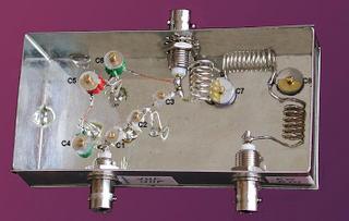
The circuit may be built easily into a metallic box measuring
abt. 11 cm x 5,5 cm x 3 cm.
Here's the circuit diagram:
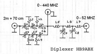
Component list: all coils 1mm dia enameled copper wire
L1 = 1 turn 5 mm (id)
L2 = same as L1, orientation 90 degr in respect to L1
L3 = 1 1/2 turn 6 mm (id)
L4 = same as L3 , orientation 90 degr in respect to L3
L5 = 7 turn 6 mm (id), 15 mm long
L6 = 11 turn 6 mm (id), 19 mm long
L7 = same as L5
C1 = foil trimmer cap. 9 pf (0.5-9 pf) see note in text
C2 = same as C1
C3 = same as C1
C4 = foil trimmer cap. 32 pf (3-32 pf)
C5 = same as C4 C6 = same as C4
C7 = foil trimmer cap. 135 pf (5-135 pf)
C8 = same as C7
3 HF chassis plugs 50 Ohm (BNC)
1 metallic box (solderable)
Coils may be made of silvered copper wire, but enameled
copper wire serves equally well.
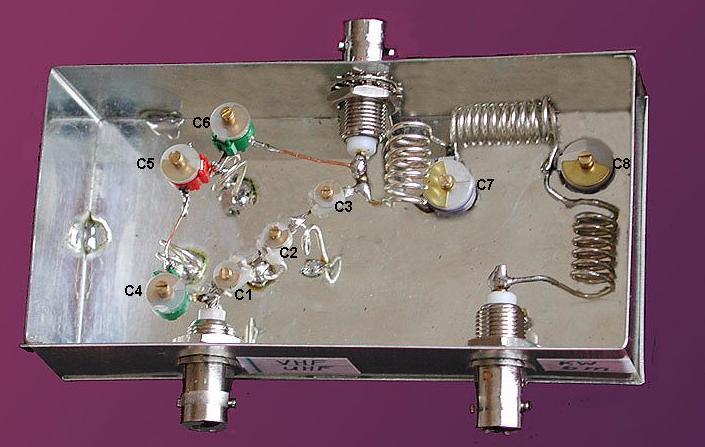
The layout should be equal, otherwise undesired coupling
may occur which hinders proper operation.
Proper adjustment of the unit is very important.
This requires some time and patiance. Prior to adjustment,
make sure that the SWR meter is calibrated exactly for
all measuring frequencies and reads exactly 1.0 when
terminated by dummy load and make sure that
dummyload is 50 Ohm on each band.
Adjustment procedure:
1. Connect 50 Ohm dummyload to plug 0 - 440 MHZ .
2. Connect SWR meter between 0 - 52 MHZ plug and
TX (51 Mc carrier low power).
(If no 6m TX available adddjust on 10m band)
Adjust C7 and C8 to obtain SWR < 1.1 .
3. Connect SWR meter between 2 m plug and TX on 2 m
(145 Mc carrier low power). Adjust C4, C5, and C6 to obtain
SWR < 1.1 . C4 and C6 should reach the same value.
4. SWR meter same as step 3, but TX on 70 cm
(435 Mc carrier low power). Adjust C1, C2, and C3
to obtain SWR < 1.1 . C1 and C3 should reach the same
value.
- Repeat steps 2 - 4 , as adjustment of one band influences
the other. You will need some patience to reach proper
adjustment on all bands!
Now your diplexer is ready for use. If an antenna analyzer
(e.g. MFJ-269) is available, use this instead of the SWR meter
and TX to make adjustment more easy. Connect analyzer
to plug 0 - 440 MHZ and dummy load to plug being adjusted.
Note: Power is limited by the capacitors. Many foil capacitors
burn at low power. Some types are stronger.
With my trimmers I tested up to 100 w on HF and 6m,
and 50w on 2m and 70 cm.
Use capacitors with higher current/voltage ratings at
higher power, e.g. good air trimmer capacitors.
Thanks HB9ABX for the above contribution!
http://home.datacomm.ch/hb9abx/diplhf6m-vuhf.html
The following DIPLEXER separates the following bands:
- HF and 6m on one side (= 0 - 52 Mc).
- 2m and 70cm on the other side.
It allows the simultaneous operation of 2 different equipments
(HF and VHF/UHF) over one coax cable, or the use of 2
antennas of the corresponding bands with one coax cable.
That means, you can operate on HF and listen or transmit at
the same time on VHF or UHF, all through the same coax cable.
It is also suitable to connect a 3 band antenna (uhf/vhf/6m) with
the antenna connectors of a transceiver as IC-706,
FT-100, or TS-2000 transceiver.
The following data was measured at 50 Ohm input and output:
- Attenuation of the other band is very high (over 60 db)
- Insertion loss is negligible (less than 0.2 db)
The circuit may be built easily into a metallic box measuring
abt. 11 cm x 5,5 cm x 3 cm.
Here's the circuit diagram:

Component list: all coils 1mm dia enameled copper wire
L1 = 1 turn 5 mm (id)
L2 = same as L1, orientation 90 degr in respect to L1
L3 = 1 1/2 turn 6 mm (id)
L4 = same as L3 , orientation 90 degr in respect to L3
L5 = 7 turn 6 mm (id), 15 mm long
L6 = 11 turn 6 mm (id), 19 mm long
L7 = same as L5
C1 = foil trimmer cap. 9 pf (0.5-9 pf) see note in text
C2 = same as C1
C3 = same as C1
C4 = foil trimmer cap. 32 pf (3-32 pf)
C5 = same as C4 C6 = same as C4
C7 = foil trimmer cap. 135 pf (5-135 pf)
C8 = same as C7
3 HF chassis plugs 50 Ohm (BNC)
1 metallic box (solderable)
Coils may be made of silvered copper wire, but enameled
copper wire serves equally well.
The layout should be equal, otherwise undesired coupling
may occur which hinders proper operation.
Proper adjustment of the unit is very important.
This requires some time and patiance. Prior to adjustment,
make sure that the SWR meter is calibrated exactly for
all measuring frequencies and reads exactly 1.0 when
terminated by dummy load and make sure that
dummyload is 50 Ohm on each band.
Adjustment procedure:
1. Connect 50 Ohm dummyload to plug 0 - 440 MHZ .
2. Connect SWR meter between 0 - 52 MHZ plug and
TX (51 Mc carrier low power).
(If no 6m TX available adddjust on 10m band)
Adjust C7 and C8 to obtain SWR < 1.1 .
3. Connect SWR meter between 2 m plug and TX on 2 m
(145 Mc carrier low power). Adjust C4, C5, and C6 to obtain
SWR < 1.1 . C4 and C6 should reach the same value.
4. SWR meter same as step 3, but TX on 70 cm
(435 Mc carrier low power). Adjust C1, C2, and C3
to obtain SWR < 1.1 . C1 and C3 should reach the same
value.
- Repeat steps 2 - 4 , as adjustment of one band influences
the other. You will need some patience to reach proper
adjustment on all bands!
Now your diplexer is ready for use. If an antenna analyzer
(e.g. MFJ-269) is available, use this instead of the SWR meter
and TX to make adjustment more easy. Connect analyzer
to plug 0 - 440 MHZ and dummy load to plug being adjusted.
Note: Power is limited by the capacitors. Many foil capacitors
burn at low power. Some types are stronger.
With my trimmers I tested up to 100 w on HF and 6m,
and 50w on 2m and 70 cm.
Use capacitors with higher current/voltage ratings at
higher power, e.g. good air trimmer capacitors.
Thanks HB9ABX for the above contribution!
posted by 9W2SSJ at
7:40 PM
|
0 comments
![]()